Transfer functions and Bode plots for Lagged derivative systems |
|||||||||||
・First-order delay system ・Transfer function ・Bode plot ・secondary delay system ・Transfer function ・Bode plot ・Butterworth filter ・Bessel filter ・Lagged derivative ・Transfer function ・Pade approximation |
・In Japanese
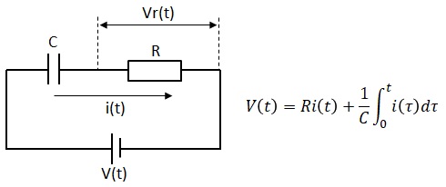
■Lagged derivative Transfer Function
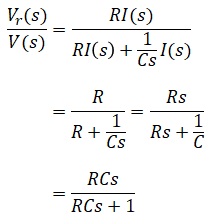
Calculate the transfer function of an lagged derivative system. As a concrete example of lagged derivative, consider the characteristics of Vr(t) versus V(t) in the following RC circuit.
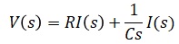
The Laplace transform of the above differential equation is as follows. ■How to draw the Bode plot of lagged derivative
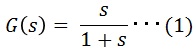
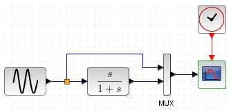
For simplicity, let us set RC=1 in the above transfer function. ■simulation result
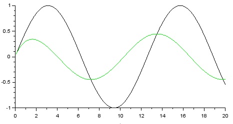
The black line is the input and the green line is the output, ω=0.5[rad/s]. You can see that the phase is advanced. However, the gain is small.
|
|
|||||||||