Transfer function of dead-time system (all-pass filter), Bode plot


Control theory

Transfer function

Analog filter
Low Pass Filter
・First-order delay system
 ・Transfer function
 ・Bode plot
・secondary delay system
 ・Bode plot
Butterworth filter
Bessel filter
All pass filter
 ・Transfer function
 ・Pade approximation
Notch filter
Band pass filter

Release date:2023/8/4         

 ・In Japanese
Premise knowledge
 ・How to draw a Bode plot
 ・Scilab


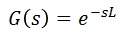
■Transfer function of the dead-time system

As below. L:Dead-time.


Substitute jω into the above equation.


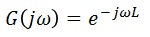
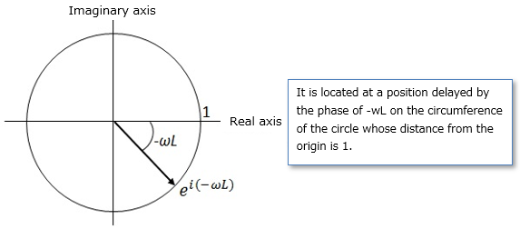
■Representation of dead-time systems on the complex plane

The above equation can be represented by Euler's formula and is located on the circle at distance 1 from the origin in the complex plane.


■Gain characteristics of dead-time system
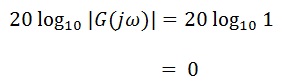
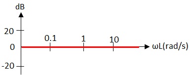
Using the decibels formula, we get:


Since the gain is always 0 dB regardless of dead time or frequency, the Bode diagram is as follows.


■Phase Characteristics of dead-time Systems
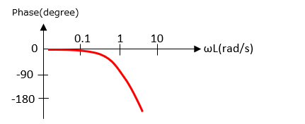
As ωL increases, the phase lags.


A filter that delays only the phase without changing the amplitude is called an all-pass filter. However, this is a nonlinear characteristic and cannot be treated as it is, so it is necessary to approximate it with an equation with linear characteristics, and one of the approximation methods is Padé approximation.

■Simulation results of dead-time system

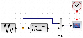
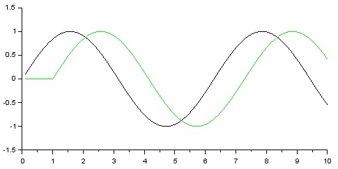
As below. Since the dead time cannot be represented by a normal transfer function block, we use a delay block.


Black is input, green is output, and you can see that only the phase is delayed.


List of related articles


Control theory

Transfer function

Analog filter
Low Pass Filter
・First-order delay system
 ・Transfer function
 ・Bode plot
・secondary delay system
 ・Bode plot
Butterworth filter
Bessel filter
All pass filter
 ・Transfer function
 ・Pade approximation
Notch filter
Band pass filter