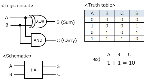
■Half adder
The half adder (HA) is a combination of an XOR gate circuit and an AND gate circuit as shown below. S (sum) is the addition result of the first digit, and C (Carry) is the addition result of the second digit.
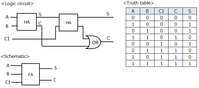
■Full adder
The full adder (FA) is a combination of a half adder and an OR gate circuit, and can handle carry from the next lower digit.
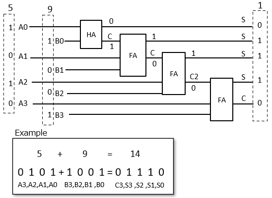
■4bit adder
If you combine a half adder and a full adder, you can calculate even if there are many digits. The result of 5 + 9 is shown as a concrete example.
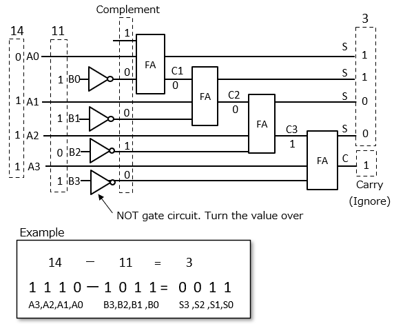
■Subtractor
The subtractor can be represented by an adder. For that, the idea of complement is needed.
Complement is when there are two numbers that make the answer of addition constant, the other number is the complement for one number.
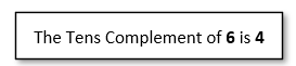
<For decimal numbers>
for example
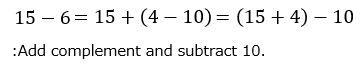
Subtraction is achieved using this complement. For example, the formula 15-6.
As mentioned above, you can add the complement and subtract the carry number of 10.
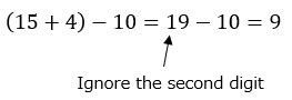
This makes it easier for a computer dealing with binary numbers to subtract 10 than to subtract 6.
Because if you ignore the second digit, it will be the same as subtracting even if you did not subtract.
<For binary numbers>
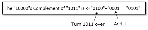
The complement is the reverse of 0 and 1 and the addition of 1 as shown below.
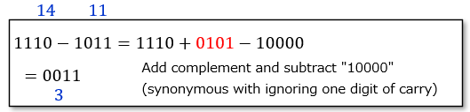
When subtracting a binary number using complement, the idea is the same as for decimal, adding the complement and subtracting the number of carry (synonymous with ignoring the number of carry).
Based on the above, the subtractor is as follows. As a concrete example, the calculation of 14-11 is shown.