Describes the H-bridge circuit.
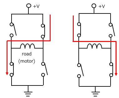
As a method of changing the direction of rotation of the motor, four switches (transistors) are combined and switched two by two.
Such a circuit is called an H-bridge circuit because it has an H shape.
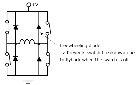
Actually, a freewheeling diode is installed in parallel with the switch as shown below to prevent switch breakdown due to flyback when the switch is off.
■Applications for H-bridge circuits
- The direction of rotation of the motor can be changed.
- Used in inverter circuits, direct current can be inverted to alternating current.
- Used for differential signal transmission in serial communication.